My Solar Water Heater
Original Unit
In 1983, I purchased a solar water heater made by Reynold's Aluminum. The unit had:
- A flat-plate collector (about 3. x 10 feet) with an aluminum absorbing surface (made of extruded tubing/fins routed back and forth through the insulated collector box). A solution of Propylene Glycol (originally Ethylene Glycol) is circulated through the collector whenever its temperature is significantly above the temperature of the water tank.
- A heat exchanger, which consists of a coil of aluminum tubing and a coil of copper tubing. The two coils are about 2 feet in diameter, and thermally joined to each other. The glycol mixture is circulated by a pump through the aluminum coil and back to the collector. Water from the storage tank is circulated by a second pump through the copper coil of the heat exchanger. The two fluid flows are in opposite directions, making this a "counterflow" heat exchanger.
- The hot water storage tank, which was basically an ordinary electric water heater with two extra holes in the top, with dip tubes, for attachment to the heat exchanger. When the pump is on, water was taken from the bottom of the tank, run through the heat exchanger, and returned to the tank. (I am certain that the extra two holes and "Solar" label on it added greatly to the selling price, if not the manufacturing cost).
The following diagram shows the layout of the system.
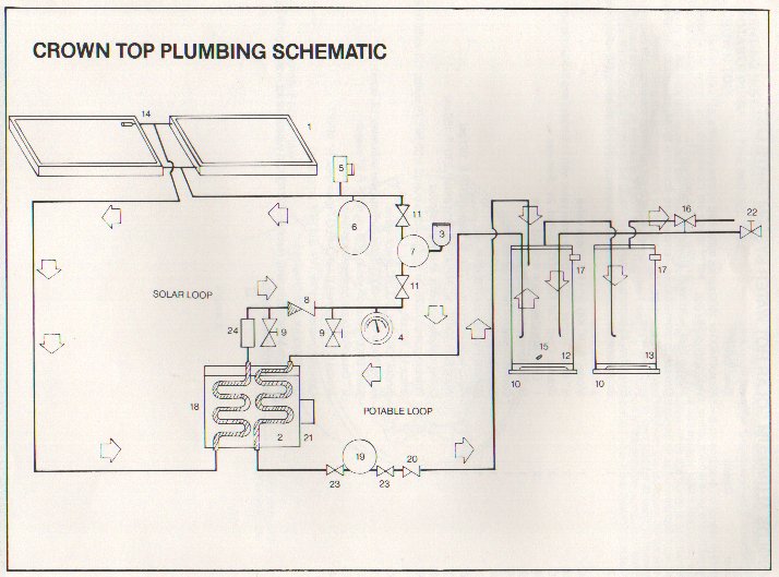
The system was installed in series with the original, 50 gallon water heater of the house. It worked reasonably well, though it was effectively only "preheat": unless water was flowing, the primary tank received no solar heat. When the original electric water heater tank went out, I just removed it and connected the solar unit as the primary heater, and connected its electric heating element. In general, the unit provided ample hot water to this household of 1 with no electric heat April through October, and partial solar hot water through the winter.
17 Years Later
In 2000, the solar storage tank showed problems. I decided to replace it. Rather than pay extra for a "Solar" unit, I decided to attempt to use a conventional electric water heater (a top of the line 50-gallon unit is available from Lowe's for about $250).
My first decision was the size. Rather than go for an 80 gallon unit, I elected to go for a 50. My reasons were as follows (and could be faulty, but too late now): The available 50 gallon tank had 3 inch insulation, compared to 2 inch for the 80 gallon tank (which the original had, too). The thinner insulation and greater surface area of the 80 gallon tank should more than offset its larger thermal mass: it was expected that the 80 gallon tank would actually cool more quickly than the 50 gallon tank. This was thought to offset the benefits of the larger tank. It is a complicated question, though.
Because the new tank had no holes for connection to the heat exchanger, I had to improvise. I connected the "input" to the heat exchanger to the drain output at the bottom of the tank. I connected the "output" of the heat exchanger to the cold water input at the top of the tank, as shown below:
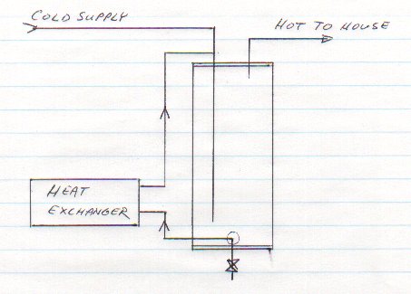
The astute individual will immediately think of a possible problem with this: a possible thermosiphon has been created by running a pipe from the top to the bottom of the tank on the outside. It will get cool, and the cooler water will sink. One can even imagine that natural convection would also be induced in the glycol loop, creating an effective nightime water cooler!
I thought about this, and decided that this was not a problem. The heat exchanger unit included a check valve that would prevent backward flow. I had even carefully cleaned and checked the check valve when cleaning up the heat exchanger unit.
Well, once installed and running, the unit heated beautifully, but it seemed to be cooling pretty well at night, too. Rather than tear it apart and work on the check valve, I just bought a new check valve and installed it in series. Surely, this would solve the problem.
It didn't. At night, the pipe out of the top of the heater was quite warm, getting cooler toward the bottom. Temperatures in the Gycol loop suggested that a secondary convection loop was active, too. Closing the valves in that loop eliminated the temperature gradient, indicating that the check valves simply were not checking.
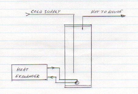
So, I decided to reengineer the whole thing. Knowing that the original convection loop was powered by a difference in elevation, I decided to attempt to circulate water both to and from the heat exchanger through the hole at the bottom of the tank. Having both connections at the same level would make thermal siphoning less likely. Having it at the bottom of the tank would make any remaining cooling less damaging. The following diagram shows the new arrangement.
I rigged up a fitting from brass and PVC parts that consisted of concentric tubes: cooler water pulled out through the outer channel and hotter water injected through the center tube. The following diagram shows the arrangement:
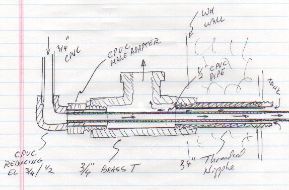
Two possibly bad effects were considered. First was that flow would be too constricted. It was guessed that the flow rate was so low that a little constriction would not be a problem. No real analysis was done. The second possible problem was that a thermal "short circuit" might be created. The thermal conductance of the CPVC center pipe was calculated, and considering the average 5 degree temperature difference between the two streams, it was judged to not be a problem (however, with a copper inner tube, it would likely be a severe problem).
Results
So far, the arrangement seems to be working pretty well. With the concentric tube arrangement, temperature relationships are about what they were before. I generally expect that glycol into the heat exchnger is about 5 degrees F hotter than glycol out. This is in turn about 5 degrees hotter than water out of the heat exchanger, which is in turn 5 degrees hotter than water into the heat exchanger. I have instrumented the system to log temperatures, and will post a graph of a typical day eventually.
Tank Heat Loss
Given what we know about the tank, we should be able to estimate the heat loss and rate of cooling. The caimed insulation rating is R19. The tank is about 24 inches across, and 48 inches high. Given 3 inch thick insulation, diameter at insulation center is 21 inches and height is 45 inches. Surface area is about 25 square feet.
Given ambient temperature of 60 F and average water temperaure of 105F, I would expect heat loss of
Q = (105F - 60F) * 25 ft**2 / R19 * 0.293 W/BTUH
  = 17 Watts.
Under these conditions I measure a temperature change of approximately 0.5F per hour. Given 50 gallons of water in the tank, and approximately 8.34 pounds per gallon, and knowing that the specific heat of water is one BTU per pound F, we can calculate that the water heater loses heat at the rate of
P = 0.5F/hr * 50gal * 8.34#m/gal * 0.293 W/BTUH
  = 61 Watts.
Although 0.5 degrees per hour is not large, it is about three times what would be expected from the water heater specs. Continuous loss of 61 watts amounts to a significant energy consumption:
Cost = 61 Watts * 24 hours * 30 days * $0.08/kWhr
     = $3.50 per month. ($42/year).
The reason for the loss is not yet clear. I am suspicious of the copper connections to the top of the tank. They always feel pretty warm. I can imagine convection currents inside of the tubes, with warm water flowing up the center and cooling water down the walls. After I investigate this, I will report the results.
It doesn't appear that convection currents to the solar unit are a problem: shutting off a valve has no effect on water cooling rate.